


I. The Role of Blowers in Petrochemical Refining Projects
During petrochemical refining processes, operating equipment requires air at specified pressure and temperature to carry out essential process treatments. Blowers are used to compress air to meet these requirements. Therefore, blower systems form a key component of petrochemical refining production equipment. The motors driving blowers generally have high power ratings and represent one of the major electrical loads in the petrochemical industry.
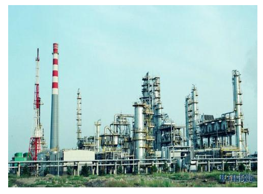
Petrochemical Refinery Exterior
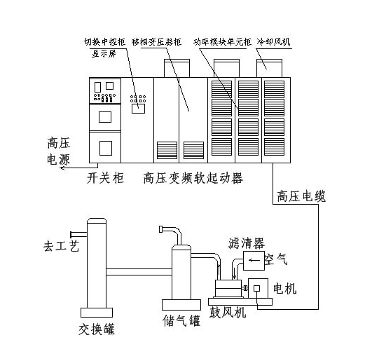
Introduction of Blower Electrical Control System and Related Equipment
High-voltage switchgears and high-voltage variable frequency soft starters constitute the high-voltage motor control system, which governs motor starting, operation and protection. The motor then drives the blower to compress air and supply the compressed gas required for refining processes. The workflow is as follows: 10kV high-voltage power is routed from the substation to the high-voltage switchgear via high-voltage cables. Power passes through the transfer cabinet and high-voltage variable frequency soft starter before reaching the high-voltage motor, to control the normal start-up and safe operation of the motor and blower. The blower compresses filtered air and delivers it to an air receiver tank, and the compressed air is then fed to refining equipment on-site in accordance with process requirements.
II. Key Parameters of the Blower and High-Voltage Power Distribution System in the Project
This project is deployed at a petrochemical refining site in Hebei Province. A Shaanxi Blower axial-flow blower is adopted, with a rotating speed of 5700 rpm. The matched motor has a rated power of 9000kW, voltage class of 10kV, rated current of 623A and locked-rotor current of 4.51 times the rated value. The motor runs at 1490 rpm and drives the axial-flow blower after speed increase through a gearbox.
For the high-voltage power distribution network: a 110kV substation supplies a dedicated 10kV feeder with a short-circuit capacity of 60MVA. The power utility sets the total project load at 16500kW. An overhead cable of 5km runs from the substation to the site, resulting in significant grid voltage drop during peak power consumption.
Simulation and analysis based on these power supply conditions and load data show that if a conventional step-down soft starter is used to start this motor (minimum starting current ≥2.5Ie), the grid voltage drop may exceed 25%. Overcurrent may also trigger grid tripping, seriously threatening the safe operation of other equipment in the system. By contrast, the high-voltage variable frequency soft starter solution keeps starting current below the rated value. It satisfies the above grid constraints and yields minimal grid voltage drop.
III. Analysis of the Impact of the Blower System on the Power Grid During Start-up
As the blower system consumes a large share of power in the whole project, starting the motor with a conventional step-down soft starter will impose severe inrush current impact on the grid. Improper configuration of starting current parameters may lead to overcurrent tripping of the switchgear and excessive grid voltage drop, disrupting normal operation of other equipment. Given the low short-circuit capacity of the grid and long transmission lines in this case, direct-on-line starting of the motor is not feasible. Even conventional step-down soft starting will result in excessive grid voltage drop or starting overcurrent, impairing the reliable operation of the blower system and other grid-connected equipment. The detailed analysis is categorized as follows:
1. The motor matched with the blower has a high power rating, accounting for over 60% of the total line capacity. A conventional soft starter produces a starting current above 1500A, exceeding the current limit specified for the grid. The grid voltage drop may exceed 25%, which exerts substantial stress on the main transformer, high-voltage lines, control switchgear and the blower unit itself. In particular, other equipment on the same grid branch must be started in advance to meet production process requirements before the motor energizes. The excessive starting current causes a severe voltage drop and may trigger overcurrent tripping. This will shut down those devices due to undervoltage or tripping, introducing major risks to the safe operation of the overall equipment system.
2. Due to the unique power supply conditions of this grid (low short-circuit capacity and long transmission lines), soft-start equipment with low starting current is required to mitigate excessive voltage drop in the weak grid. The high-voltage variable frequency soft starter meets this requirement. It ensures the motor starting current stays below 500A (less than rated current), with grid voltage drop limited to approximately 2%, bringing no impact or disturbance to the project’s electrical equipment system.
3. Adoption of the high-voltage variable frequency soft starter also cuts equipment capital investment and operating costs. Based on the existing setup, it can reliably resolve motor starting and power consumption issues of other equipment without additional hardware investment. There is no need to expand the substation capacity, which would otherwise raise operating expenses.
IV. Specific Application of High-Voltage Variable Frequency Soft Starter in This Engineering Solution
1. Model Selection of the High-Voltage Variable Frequency Soft Starter
To meet the requirements of this project, after multiple rounds of communication and technical exchanges between both parties, the Dayu Electric GBRQ-10000-10/10-B high-voltage variable frequency soft starter with a voltage class of 10kV was selected based on the motor parameters of 9000kW rated power and 10kV voltage class. This unit can satisfy the start-up requirements.
The blower is a conventional load, and the motor locked-rotor current of 4.5 times rated value is relatively moderate. Therefore, standard-rated main components of the variable frequency soft starter are sufficient to meet on-site start-up demands and deliver favorable starting performance. It is worth noting that the high-voltage variable frequency soft starter shares the same control principle as the high-voltage frequency converter, yet their selections of main components differ.
2. Start-up Performance of the High-Voltage Variable Frequency Soft Starter in This Engineering Solution
After the equipment arrived on-site and completed intensive installation and commissioning, the actual start-up parameters of the high-voltage variable frequency soft starter are as follows: starting current of 460A, start-up duration of 190 seconds, and grid voltage drop of approximately 1.5%. When the motor completes start-up and switches to normal operation mode, no voltage or current fluctuation or surge occurs on the power grid. The system fully meets the technical design specifications.
V. Description of High-Voltage Variable Frequency Soft Starter Control Scheme for the Project
1. System Control Schematic and Operating Sequence
In accordance with the user’s motor parameters and grid configuration requirements, this project adopts a 10000kW, 10kV high-voltage variable frequency soft starter. The primary circuit scheme is shown in the figure below. The system operating process is described as follows: After the high-voltage switchgear and high-voltage variable frequency soft starter are ready, the low-voltage auxiliary power supply is energized and automatic self-check completes normally. The high-voltage variable frequency soft starter sends a close-permission signal to the switchgear.
Once high-voltage switchgear QF1 closes, transfer switches QF3 and QF4 close automatically in sequence to start the high-voltage variable frequency soft starter. The soft starter outputs working voltage with adjustable frequency and amplitude, and the motor begins to rotate slowly. After speed ramp-up, when the output voltage of the high-voltage variable frequency soft starter approaches the power frequency, a 2-second delay is triggered. Then QF3 and QF4 open simultaneously, the running switch QF2 closes, the motor transfers to power-frequency operation, and the high-voltage variable frequency soft starter automatically exits from the starting loop.
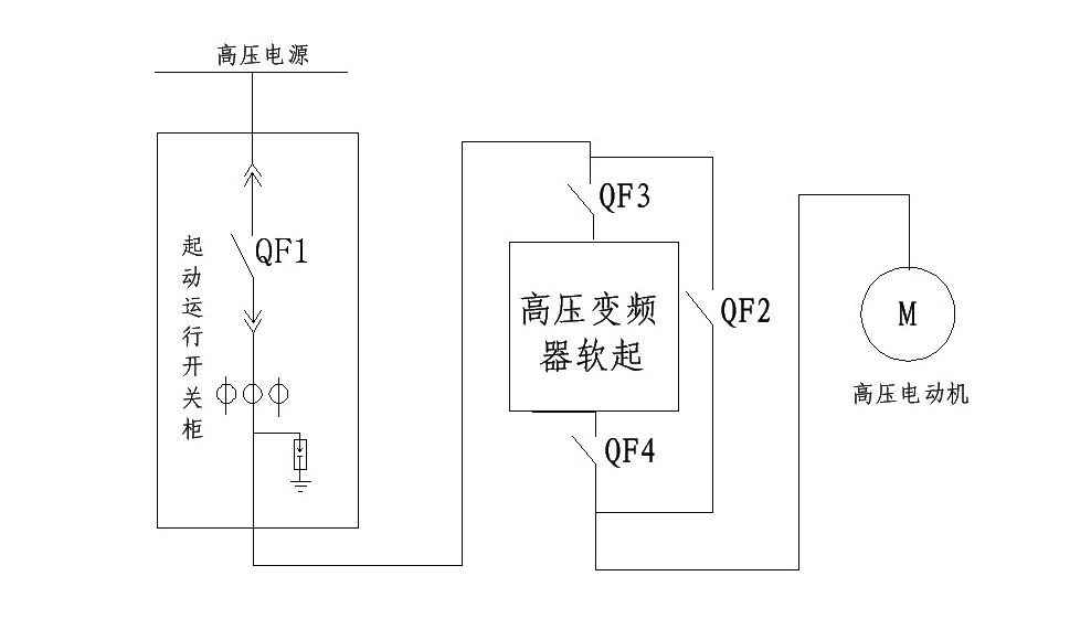
Primary Scheme of High Voltage Variable Frequency Soft Starter
2. Introduction of Main Equipment and Configuration in the System Scheme
①Start & Operation Switchgear: It adopts KYN28 cabinet type and serves as the protection switch for start-up and normal operation of the high‑voltage variable frequency soft starter.
②Transfer & Central Control Cabinet: It consists of two major parts. The front panel is equipped with the central control unit of the variable frequency soft starter, display screen and pushbuttons. At the rear of the cabinet, QF3 and QF4 are connected in series with the variable frequency soft starter to form the starting loop; QF2 is the bypass power-frequency running switch.
③Phase-shifting Transformer Cabinet: A phase-shifting transformer is installed inside the high‑voltage variable frequency soft starter cabinet, with cooling fans mounted on the cabinet top.
④Power Module Unit Cabinet: Multiple sets of power module units are installed inside the high‑voltage variable frequency soft starter cabinet. The modules are connected in series phase by phase, and output three-phase power to the motor. Cooling fans are also fitted on the cabinet top.
